Thursday, September 5, 2013

Qatar

Colleagues,

At the end of this month I will be relocating to Doha, Qatar to serve as Senior Architect and BIM Manager for a sports complex renovation.

I will be working for project manager KEO International Consultants. The design consultant is AECOM, project designer Zaha Hadid Architects.


Monday, August 19, 2013

Finding the Efficiency of BIM

Revit Model
With two weeks until first building department submittal, our "GA" apartment project has steadily evolved since the decision to continue using BIM was made. We now have three Reviteers involved.

The GA project is a large stacked flat apartment building. We have evolved a method that incorporates groups, links, design options and phasing to achieve the maximum efficiency in creating and managing the BIM for construction documents.

SketchUp Model
In multi-family housing CADthe design development process relies on surface modeler SketchUp. While most agree it is a "great design tool", the model is not connected to the plan development, and frequently loses its fidelity.

Projects often receive client or agency approval in spite of inconsistencies. When a project moves from DD to CD, the 2D plan files developed by the designers are handed over to production staff who refine the building plans and develop construction documents. It is they who must decipher or verify the "design intent" while applying their knowledge of building codes and constructability. The redundancy and inefficiency in this process is apparent. The obvious solution is to use the same program for both modeling and plan development. That is the reason that BIM and Revit exist.

Are designers really challenged by the process change required to switch from SketchUp to Revit? It is a move which offers many benefits. For those not familiar with the MacLeamy Curve, one effect of BIM is that effort is shifted forward where the  ability to impact cost and functional change is greater, and the cost of making changes is less.

Repeat: The cost of making changes is less.

In the technologically held back housing industry, the perceived additional effort to start up a Revit project at the CD stage is a difficult sell, especially when the client has not requested it. 


Vasari is an alternative
for concept design.
The efficiency of BIM is found in moving the effort forward where the cost is less. Designers should be eager to to accept the challenge of learning new methods, when there are benefits for all involved.


Once the basic building form has been conceived, designers must evolve the aesthetic concept, optimize dwelling unit mix and design, and provide accommodation for the infrastructure, services and common facilities.


The arrangement of the various unit types has significant impact on the building's form. Using mass families these unit types may be modeled as multi-story elements that can be driven parametrically to analyze and optimize the building design. Over time a library of plan types and plan forms will be developed that may be combined to rapidly complete the plan development. 

The mass family is also the basis for development of building modules that will be linked into a host model. At this stage design options may be used to explore and evaluate different material and finish options. With this method, "skinning" the building is achieved by manipulating the unit type model and propagating geometry and material changes throughout the model.

Groups are used for the interior of each unit type model to assure floor-to-floor consistency and modeling efficiency.

Revit is very entrepreneurial, and even within the same company, there are often as many modeling strategies as there are modelers. Methods also vary depending on the type of project. My goal is always to improve both the process and the product. The knowledge gained will be applied to subsequent projects, regardless of type.

Saturday, June 22, 2013

Revit to CAD - Nothing to Fear


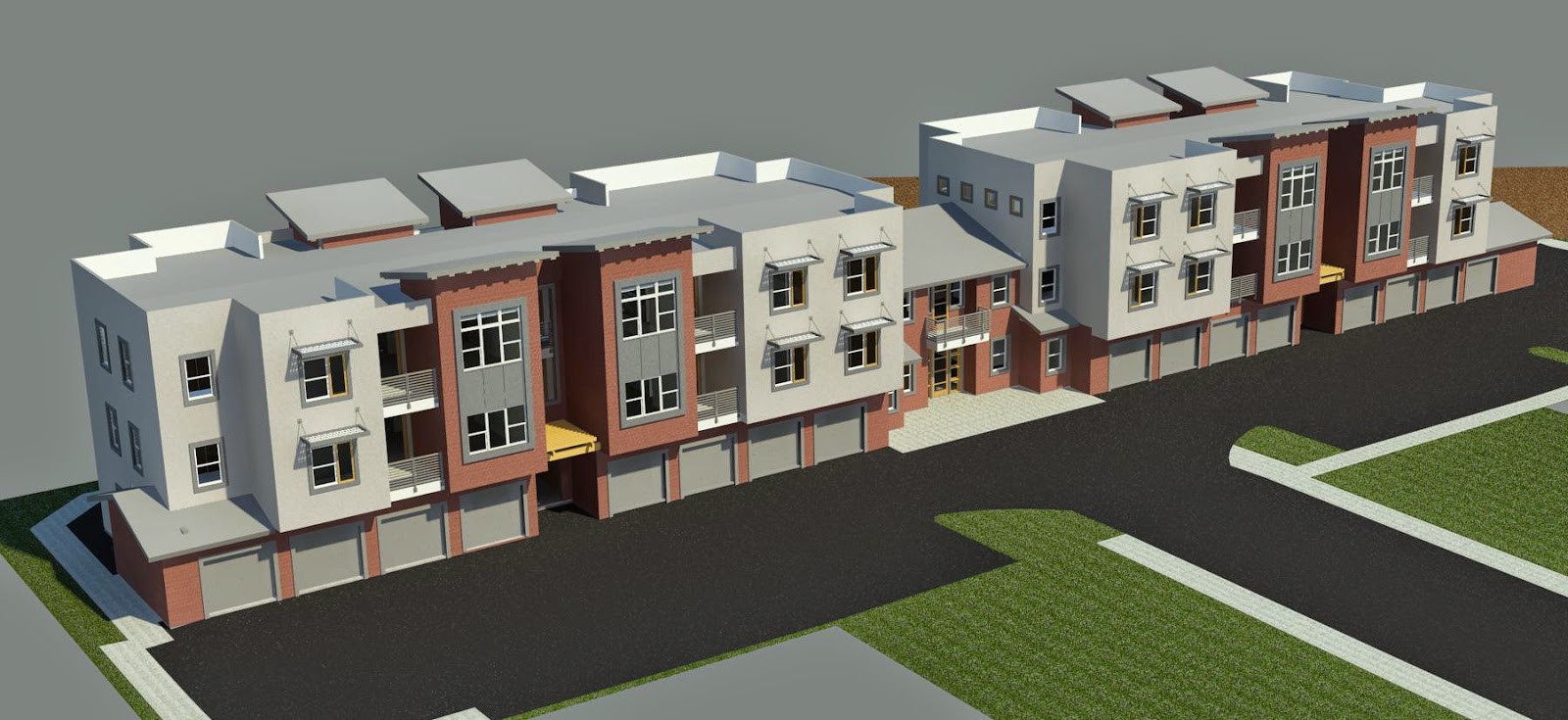
We are well on our way to our goal of 50% DD on our new 'GA Apartment' BIM project, with a well developed model, fifty sheets set up, and the first round of CAD backgrounds issued to consultants. 80 hours.
Our largest BIM housing project so far was nearly derailed during a kick-off meeting with the owner's MEP consultants. I was not present (perhaps I should have been) but it was reported that these CAD based designers were upset about the extra effort involved in working with CAD files exported from a Revit model. One claimed that they would need to add 4 weeks to their schedule because of problems they have had with some other architect's BIM output. Of course this is just fear the unknown - were have not yet provided anything. (Owners take note - if the work were being done with BIM, this would be a non-issue.)

It was stipulated that unless we can provide backgrounds and sheet layouts that look exactly like our standard 2D files, the project will revert to CAD. I did not hesitate to guarantee that will not happen. I further guaranteed that the export will be better than, not equal to, the typical 2D output.

Internally, we had previously discussed that the 'OOTB' Revit export setup produces files that conform to the AIA Layer Standards, which is also the basis for our office standard. To placate those who cannot seem to conceive of walls with finishes, we had further decided modify the export setup to place the finish material line work on separate layers, allowing these items to be hidden or deleted.

The main problem with CAD standards is they DO NOT WORK. We have a very well documented office standard that defines layer names for every type of "object" in the 2D world. We also have a table listing all of the approved line colors and their corresponding line weights. I randomly chose one base plan file from the project's "xref" directory and easily discovered violations of both these "standards". Non-standard layer names and colors.

With the typical "x-clip/xref" methodology, there are literally hundreds of layers to manage - one set for every instance of every unit plan, plus many other random layers - more than six hundred layers in all.

The CAD exported from the Revit model is completely consistent and reliable. The options for CAD export are explained very well by Steve Stafford in this Revit OpEd post,
"It is important to understand that the intended purpose for exporting to DWG is to create files that can be used as a background for other trades. It was never really intended to be a better way to make DWG files."
In the export dialog Revit categories are mapped to layer names and colors in CAD. I actually had to "dumb down" the standard export setup, combining items that would normally be on separate layers.


For export to our specific office layer standard, line weights are controlled using color by layer:


In the Visibility Graphics dialog, Cut Line Styles allows adjustments of lines weights of host objects (floors, walls, ceilings & roofs) which affect both display and export.


While some fine tuning remains, we achieved the goal of providing CAD base drawings with separate layers for finishes (which do not exist in the normal CAD world!) Overall the output is better. 689 layers in a typical CAD floor plan base are reduced to thirty-one - yet CAD is the "industry standard" that is defended, against the elegant, simple, consistent output created by Revit.

Strange but true.


Monday, June 3, 2013

Multi-Family Housing Concepts

When I became immersed in the housing industry and began studying its processes, my original strategy for implementation was to emulate the methods being used with CAD, to make the transition to BIM easier. That strategy has evolved over several months, and each new project is an opportunity to improve the the process and the outcome.


Housing is similar to high-rise hospitality, where repetition of the individual units within a structural bay is the key to efficiency, in the modeling process as well as in actual construction. This repetition allows the unit mix within a hotel or condo tower to be adjusted late in the design process, or perhaps during construction, in response to project conditions. In tower BIM the individual unit models typically do not include the building enclosure (although this has been done).


Low-rise, Type V mixed-use and multifamily housing differs in that, unrestricted by a structural grid, the unit shapes and sizes vary greatly, and in design the pieces must be assembled like a jigsaw puzzle, to achieve the desired unit mix. Within the individual unit types, there may be variations based on story level or exposure, including windows, railings, balconies and other interior and exterior features.

In construction, these buildings are "stick framed" with bearing walls, simple span floor joists, and roof trusses. They are very simple buildings.
  • The benefit of BIM to builders is the refinement of the design to eliminate surprises in the field. Surprises lead to changes, delays, and loss of efficiency.
  • The benefit of BIM to designers is that a building prototype may be rapidly assembled with many variations tested to achieve the optimum design configuration.
  • The benefit of BIM in production is rapid composition of construction documents that are coordinated and graphically consistent.
For the RW Apartment project, in less than 40 hours, using previous projects as a resource, we already have a prototypical CD package that could pass for 50% completion. 40 sheets in all. Starting a residential BIM project from CAD and Sketchup files is quick and easy. Anyone with Revit construction knowledge can do it. Imagine how productive and profitable it is when these techniques are successfully pushed "upstream".


Modeling Notes~
It is tempting to try assembling an entire building from groups or linked files. While this is a great way to start, for a "stacked flats" project it must eventually be abandoned - especially when using groups.

A residential building's exterior walls vary in their height, materials, and openings.
Once the basic form is generated, it seems best to remove these items from their groups. We start with "core only" walls for layout, but these are quickly replaced by components with specific materials and finishes.

At the building level, the largest repeatable segment was identified as the entire building enclosure, consisting of roof, walls, floors, windows, doors, stairs and railings.


At the unit level, the largest repeatable segment consists of interior elements and exterior features, including windows, that do not vary from floor to floor. The key with these interior groups is that all objects must share the same reference level. Interior groups are independent; they are not nested into the larger building group.

Door and window style schedules developed on previous projects allowed rapid assignment of those components based on room type.

Friday, May 31, 2013

It's Not Rocket Surgery

I met Phil Bernstein at an AIAOC event several years ago. I was astonished when he projected ten more years before BIM would fully penetrate the profession.  Already working on the bleeding edge of architectural technology for several years, that estimate was beyond my belief. That was thirteen years ago.

I visited his blog and was refreshed to learn that someone is thinking about architectural at a much higher level than is common in our daily professional lives:
"How do we make design a more profitable practice? Design practice has traditionally positioned building as a commodity in the delivery supply chain, valued by clients like other products and services purchased at lowest first cost. Intense market competition, sole focus on differentiation by design quality, and lack of innovation in project delivery models and and business models, has resulted in a profession that is grossly underpaid and marginally profitable, despite the fact the building sector in its entirety operates in large capital pools where significant value is created. The profession must explore new techniques for correlating the real value of an architect's services to clients and thereby break the downward pressure on design compensation."
This is the purpose of the BIM-4-Homebuilders conference. To learn what your colleagues and peers are thinking as well as what they're doing with regard to BIM. Those who have been to our SCRUG meetings know that the real purpose of the meetings is networking. At this event it will be on a grand scale, amid a 30 million dollar collection of exotic cars - and the proceeds of the event go to charity.

Owners, designers, builders, and consultants all may have differing ideas about BIM. What is it? What does it do? What is it's value? What is it for?
Why has this sector resisted change?
  • After a brutal economic downturn, workers are grateful  to be employed, and reluctant to "rock the boat".
  • It took years to get designers to give up their pencils - now they're stuck on Sketchup, the "hollow" modeler. Most designers show no interest in advancing the technology. Most are simply waiting to be told what to do.
  • Practitioners have streamlined the CAD process beyond efficiency to minimalism. "We don't show that on our drawings" is a common instructional phrase. Coordination is one direction: downstream. It is up to the consultants to keep their work up to date. Conflicts are resolved in the field.
My part in all this is to teach - to anyone who will listen - how easy, how satisfying, and how rewarding it is to build with BIM. All the work depicted in the video above, and much more, was accomplished in two days time. Wall and floor types; custom windows and awnings, materials. Coordinated civil data; imported topographic data. As of today the first wave of design refinements has been implemented. 

We proceed with the confidence that all of this information is coordinated and up to date. We are gradually accumulating a library of components and prototypes, and a repertoire of methodologies, that must eventually be moved upstream, to realize its full value. Those who resist are likely to be overwhelmed. 

Who believes that this is difficult is not aware. 

To join your peers and colleagues in this process of change, please register for the BIM-4-Homebuilders conference today.

Thursday, May 23, 2013

The End to CADdiction?


At the end of its design development phase, a current project hangs in the balance between CAD and BIM. This study was commenced in an attempt to influence the direction of that decision. 

The "GA" Apartment project was earmarked as a possible Revit/BIM project several weeks ago. Because of its impending launch into the CD phase, it was important to formulate and test the intended methodology for the accomplishment of that task using Revit.

A breakthrough concept that has evolved over the last several projects is the understanding that the highest efficiency can be gained by modeling the largest repeatable segment of the building. On this type of project, it is the entire "stack" of units of the same type.

A review of the project reveals that there are only six distinct unit types, and that these unit stacks occur in 2, 3, 4 and 5 story configurations. The interior of the units are identical on every level, while the building exterior envelope may vary based on story level and interior or end condition.


A variable height mass component family was created for each unit type. This is simply the unit footprint, extruded vertically. Each family is color-coded. When placed in a massing model, these height of these components may be varied parametrically. A complete massing model may be quickly assembled by placing these 3D families, and filling in the interstitial spaces for circulation and other services.


These components, of course, contain basic area and volume data which may be scheduled. Over time, a library of the many variations that are generated during design will be assembled, reducing repetition and further accelerating the project development process.

The next step in bringing the project to life involves the creation of the stacked unit model. For this exercise the most typical unit type was selected. The mass family is loaded into a separate project file. Walls, floors, and roofs are created by selecting the faces of the massing model. Next, doors, windows, decks and railings are added. Objects that repeat from level to level are grouped for consistency and efficiency. Roof slope is assigned and parapet walls are extended vertically. Finally exterior materials are specified.


These refined stacked unit models replace the massing families in the composite building model. Variations may be depicted using design options.


For the building site model, existing topographic data was imported into Revit. The topo surface model is created automatically. Revit’s phasing feature allows refinements of the model, and reports approximate cut and fill quantities.


There is no debate about the value of Building Information Modeling. That has been realized for many years by countless practitioners on projects of all types. BIM is the obvious choice for design and construction professionals whose goals include the delivery of accurate and well coordinated contract documents. This can, of course, be achieved with the current system, but only with a high degree of discipline involving knowledge that has nothing to do with architecture. BIM assigns that responsibility to the software program, and allows users to focus on their specialty, whether it be management, design, or production. A small percentage of owners and builders now require BIM, but its benefits accrue to every project stakeholder, regardless of their level of knowledge or participation.

BIM can be used solely for production, but the maximum benefit comes from moving its application "upstream". For most homebuilding architects, the design work flow involves Sketchup and CAD. The main flaws of this methodology are that the models are hollow and contain no volumetric data; secondly, it (again) requires great discipline to keep the two programs in sync, until the goal is eventually abandoned.

The mass modeling capability of Revit is equal to Sketchup, and in the process described here, leads to a rapid and efficient development process, and an accumulation of resources which are easily accessible across all studios, offices, and project types.


Monday, April 29, 2013

Walk-Through Study

This study of a current project was created at the client's request, to aid in visualizing an important area of the building, which was not addressed in the SketchUp Design Development model.


An in-place massing model was created using CAD backgrounds.

Walls were added in the area of interest using 'Wall by Face'.


Doors, windows, decks, and railings - salvaged from other projects - were added in the focus area only.

Topography placed in the courtyard area, with various materials placed by sub-region, using a landscape background as the template.


A 'fly-in' animation sequence was created by manipulating camera path key frames in a section view.

A 'fly around' animation sequence was created using 3D lines as a template for the path. Key frames were added to smooth out the camera motion.


The two animation sequences were aligned by placing the views on a sheet in wire-frame mode. All camera adjustments were made using the 'Look' feature on the Revit Steering Wheel. The two sequences were then combined with titles and effects using Windows Movie Maker.


Monday, April 8, 2013

Site Specific Design Options


Adopting BIM to replace CAD is more than just learning this new tool. The tool is intended to do a slightly different job, and so it may not fit into your hands in just the same way.

In residential projects with multiple buildings, whether single or multi-family, one of the expediencies forced by CAD is that every instance and variation of every building is not fully documented. There is a ripple effect throughout the drawings. Changes must be followed through. And this is where the weakness of CAD becomes too obvious to ignore. It is extremely inefficient when it comes to the minor adjustments and fine tuning of the drawings. And so we do not do it. Because of CAD.

The logic is that since we are not responsible for the vertical placement of buildings on a site – that is the civil engineer’s task – we cannot possibly be asked to keep up with such changes. Instead we frequently refer to someone else's drawings, and it's up to the builder to put it all together in the field.

In the Playa Vista project, the documentation for all six buildings on the site is generated from a single model. The efficiency of using groups with Design Options is described in the previous post.

Building sites are never flat. In residential building, the threshold of the garage is always at least six inches below the finish floor level. The minimum standard is a four inch step and two inches of slope (one percent). 


In single family, the step-down may be increased to adapt the building to a sloping site. With larger buildings, in addition to the garage step-down, sometimes the entire floor slab must be offset, or even the entire building. Although these decisions are not within our scope, we are required to depict this information on our drawings.


Experimentally, for Playa Vista we added six new options to the three original "prototypical" ones which are depicted in the construction drawings. It was very easy to divide the slab, slope the garage floors, and add wall curbs where required.


The accurate depiction of each variation is important because of three stairs which may require adjustment, where headroom, landing depth and handrail extensions clearances are critical. Additionally, detailing around the base of the building must be coordinated where the lower slab offset may be as much as twenty-one inches below the main floor.

Wednesday, March 27, 2013

Quick QAT


A quick tip to speed up Revit work flow is to move the Quick Access Toolbar below the menu ribbon.

It should probably be there by default. I've noticed that many users overlook it at the top. To move it simply select the option at the bottom of the drop-down.

The Out-of-the-Box commands are as shown.


Add almost any command to the QAT by right-clicking... 


My personal favorite is to place the Type Selector drop-down on the QAT. Because the interface is context sensitive, alternatives to the object currently selected are shown immediately above the work space.

For the Playa Vista project described in the previous post, which was heavily dependent on Design options, placing the 'Pick to Edit' tool on the QAT was an incredible time saver when working among the various options in the model.


Sunday, March 24, 2013

Design Options & Groups


I am working with two teammates on a project for Brookfield Homes, the unequivocal leader among home builders who have embraced Building Information Modeling.

My colleague Louis Navarette is responsible for the development of Brookfield’s BIM Guidelines, families and template files which are provided to the architects and engineers who serve them. While the performance guidelines are very strict, specific methods are at the discretion of each designer.

Exterior Styles
The Playa Vista project consists of six four-story buildings - three dwelling levels over a garage level. There are two different building configurations. Four of the buildings contain six dwelling units; there are also two "tri-plex" buildings, which are derived by removing three smaller units from the larger building, while maintaining the main lobby and both exit stairs.

There are also two separate exterior treatments – A & B. Some exterior elements are shared by the two larger buildings only (6A & 6B). Other elements are shared between the larger and smaller buildings of the same style (3A & 6A). It was apparent from the beginning of the project that Design Options should be employed.

Design Options in Revit is intended for the depiction of several alternates or variations of a base model. The Design Options interface manages the display of the model based on the selected option. Only elements that change are placed into the option. Objects that occur in all three buildings are not duplicated – they reside in the “main model”.

Exterior Groups
During the course of our work, it became apparent that, for the most efficient modeling process, elements that were shared by two of the three options could be placed in Revit groups. When the group is edited, changes are automatically propagated to both versions, eliminating duplicate effort while insuring that design continuity is maintained.

Interior Groups
While there are three exterior options, the interior of buildings 6A & 6B are identical. For further efficiency, we decided to place the building's interior components (partitions, doors, plumbing fixtures, etc.) into a separate design option. Interior components that are identical from floor to floor are also grouped so that interior changes are also automatically propagated throughout all floors and styles.

When Design Options are activated, an additional tab is displayed in the Visibility/Graphic Overrides dialog. When set to Automatic, the model view displays the active option. For ease of editing, the template provided by Brookfield contains Working Views that may be pre-set to the desired combination of options.
There are two built-in filters to aid working with Design Options. When 'Main Model' is selected, individual elements within an option may be modified by unchecking the box labeled 'Exclude Options'. 
When a Design Option is active, elements in the main model may be edited by unchecking the box labeled 'Active Only'.
With a team of three on the project, the work flow was uncomplicated. Typically it was one person on the interior, one on the exterior, and one in a separate Composite Document file. Overall I am very satisfied with the methodology that evolved for this project, and intend to use it as a prototype for the next one.